|
|
|
||||||||||||||||||||


|
|||||||||||||||||||


 물품구매안내")


 톡톡
톡톡- 라즈베리파이 학습에 필요한 키트 및 부품
-
[로봇사이언스몰][Pololu][폴로루] Pololu Dual G2 High-Power Motor Driver 18v22 for Raspberry Pi (Partial Kit) #3754
상품번호 : 12038 아이콘 설명보기
![[로봇사이언스몰][로봇사이언스몰][Pololu][폴로루] Pololu Dual G2 High-Power Motor Driver 18v22 for Raspberry Pi (Partial Kit) #3754>>라즈베리파이 학습에 필요한 키트 및 부품](/data/goods/1/2018/03/12038_tmp_e9b3fbeb094bdc470d243f1da36bdcbd1671view.jpg)
![[로봇사이언스몰][로봇사이언스몰][Pololu][폴로루] Pololu Dual G2 High-Power Motor Driver 18v22 for Raspberry Pi (Partial Kit) #3754>>라즈베리파이 학습에 필요한 키트 및 부품](/data/goods/1/2018/03/12038_tmp_a3da3bc49524d70957c16933c7adddd56877view.jpg)
![[로봇사이언스몰][로봇사이언스몰][Pololu][폴로루] Pololu Dual G2 High-Power Motor Driver 18v22 for Raspberry Pi (Partial Kit) #3754>>라즈베리파이 학습에 필요한 키트 및 부품](/data/goods/1/2018/03/12038_tmp_48e7e86f3dea9bec6ae655eacaec29fb8956view.jpg)


[로봇사이언스몰][Pololu][폴로루] Pololu Dual G2 High-Power Motor Driver 18v22 for Raspberry Pi (Partial Kit) #3754
18v22 for Raspberry Pi |
18v18 for Raspberry Pi |
24v18 for Raspberry Pi |
24v14 for Raspberry Pi | |
|---|---|---|---|---|
| Absolute max input voltage: | 30 V | 36 V* | ||
| Max nominal battery voltage: | 18 V | 28 V | ||
| Max continuous current per channel: | 22 A | 18 A | 18 A | 14 A |
| Default active current- limiting threshold: | 60 A | 50 A | 40 A | |
| Available with connectors installed? | No | Yes | No | Yes |


* 40 V if regulator is disconnected
This add-on board makes it easy to control two high-power DC motors with a Raspberry Pi. Its twin discrete MOSFET H-bridges support a wide 6.5 V to 30 V operating range and are efficient enough to deliver a continuous 22 A without a heat sink. The drivers offer basic current limiting functionality, and they accept ultrasonic PWM frequencies for quieter operation. The default pin mappings make it easy to get started, but they can be customized for more specialized applications. This version ships as a partial kit; all surface-mount components are installed, but the included through-hole connectors are not soldered in.
Overview

The minimum operating voltage for all four versions is 6.5 V, while the maximum operating voltages are given in the above table. The board also includes an integrated 5 V, 2.5 A switching step-down regulator that can be used to power the Raspberry Pi it is plugged into, enabling operation from a single power supply.
The driver’s default configuration uses six GPIO pins to control the motor drivers, making use of the Raspberry Pi’s hardware PWM outputs, and it uses two additional pins to read status outputs from the drivers. However, the pin mappings can be customized if the defaults are not convenient, and pins for current sensing and limiting are accessible on the board for more advanced applications.


Note that this motor driver add-on is designed specifically for newer versions of the Raspberry Pi with 40-pin GPIO headers, including the Model B+, Model A+, Raspberry Pi 2 Model B, and Raspberry Pi 3 Model B. The board matches the Raspberry Pi HAT (Hardware Attached on Top) mechanical specification, although it does not conform to the full HAT specifications due to the lack of an ID EEPROM. (A footprint for adding your own EEPROM is available for applications where one would be useful; pull-ups on SDA, SCL, and WP are provided.) It is not practical to use this expansion board with the original Raspberry Pi Model A or Model B due to differences in their pinout and form factor.
These dual motor drivers are also available as Arduino shields. For single-channel versions in a more compact form factor, consider our High-Power Motor Drivers. For smaller, lower power, and lower cost alternatives designed for a Raspberry Pi, consider our Dual MC33926 Motor Driver for Raspberry Pi and DRV8835 Dual Motor Driver for Raspberry Pi.
Features common to all versions
Details for item #3754


The following through-hole connectors and mounting hardware are included with the board, which ships with its surface-mount components populated:
The 2×20-pin 0.1″ female header should be mounted to the bottom of the board (the side opposite the surface-mount components). Once soldered, this header is used to connect the board to the Raspberry Pi’s 40-pin GPIO header. Alternatively, if you want to continue to have access to the Raspberry Pi’s 40 GPIO pins while the motor driver board is plugged in, you can install a stackable 2×20-pin female header (not included) instead.
You can solder the terminal blocks to the six large through-holes to make your motor and motor power connections, or you can solder a 0.1″ male header strip (not included) into the smaller through-holes that border these larger holes. Note, however, that the terminal blocks are only rated for 16 A, and each header pin pair is only rated for a combined 6 A, so for higher-power applications, thick wires should be soldered directly to the board..

Shorting blocks and 0.1″ male headers (not included) can be used to make some of the more advanced optional modifications to the board, such as remapping the control pins.
The motor driver includes six 100 μF or 150 μF electrolytic power capacitors, and there is room to add additional capacitors (e.g. to compensate for long power wires or increase stability of the power supply). Additional power capacitors are usually not necessary, and no additional capacitors are included with this motor driver.
A Raspberry Pi is not included.
Using the motor driver board

Power

By default, the motor power supply also feeds a 5 V, 2.5 A switching step-down regulator that provides power to the connected Raspberry Pi. An ideal diode circuit makes it safe to have a different power supply connected to the Raspberry Pi through its USB Micro-B receptacle while the motor driver is connected and powered.
If you want to power the Raspberry Pi separately, the regulator can be disconnected by cutting two exposed traces on the board: one between the surface-mount pads labeled “VM” and “REG IN”, and another between the two pins by the “REG OUT” label, as shown to the right. On the 24v14 and 24v18 versions, disconnecting the regulator increases the absolute maximum operating voltage of the board to 40 V.
Default pin mappings
This table shows how the Raspberry Pi’s GPIO pins are used to interface with the motor drivers:
| RPi GPIO pin | Motor driver pin | Description |
|---|---|---|
| 5 | Motor 1 FLT | Fault indicator: When the driver channel is functioning normally, this pin should be pulled high by the Raspberry Pi. In the event of a driver fault, FLT is driven low. See below for details. |
| 6 | Motor 2 FLT | |
| 12 | Motor 1 PWM | Motor speed input: A PWM (pulse-width modulation) signal on this pin corresponds to a PWM output on the corresponding channel’s motor outputs. When this pin is low, the motor brakes low. When it is high, the motor is on. The maximum allowed PWM frequency is 100 kHz. |
| 13 | Motor 2 PWM | |
| 22 | Motor 1 SLP | Inverted sleep input: This pin is pulled low by default, putting the motor driver channel into a low-current sleep mode and disabling the motor outputs (setting them to high impedance). SLP must be driven high to enable the motor channel. |
| 23 | Motor 2 SLP | |
| 24 | Motor 1 DIR | Motor direction input: When DIR is low, motor current flows from output A to output B; when DIR is high, current flows from B to A. |
| 25 | Motor 2 DIR |
Motor control options
With the PWM pin held low, both motor outputs will be held low (a brake operation). With PWM high, the motor outputs will be driven according to the DIR input. This allows two modes of operation: sign-magnitude, in which the PWM duty cycle controls the speed of the motor and DIR controls the direction, and locked-antiphase, in which a pulse-width-modulated signal is applied to the DIR pin with PWM held high.
In locked-antiphase operation, a low duty cycle drives the motor in one direction, and a high duty cycle drives the motor in the other direction; a 50% duty cycle turns the motor off. A successful locked-antiphase implementation depends on the motor inductance and switching frequency smoothing out the current (e.g. making the current zero in the 50% duty cycle case), so a high PWM frequency might be required.
| Inputs | Outputs | Operation | |||
|---|---|---|---|---|---|
| SLP | DIR | PWM | MxA | MxB | |
| 1 | 0 | PWM | PWM (H/L) | L | forward/brake at speed PWM % |
| 1 | 1 | PWM | L | PWM (H/L) | reverse/brake at speed PWM % |
| 1 | X | 0 | L | L | brake low (outputs shorted to ground) |
| 0 | X | X | Z | Z | coast (outputs off) |
PWM frequency
The motor driver supports PWM frequencies as high as 100 kHz, but note that switching losses in the driver will be proportional to the PWM frequency. Typically, around 20 kHz is a good choice for sign-magnitude operation since it is high enough to be ultrasonic, which results in quieter operation.
A pulse on the PWM pin must be high for a minimum duration of approximately 0.5 µs before the outputs turn on for the corresponding duration (any shorter input pulse does not produce a change on the outputs), so low duty cycles become unavailable at high frequencies. For example, at 100 kHz, the pulse period is 10 µs, and the minimum non-zero duty cycle achievable is 0.5/10, or 5%.
Fault conditions
The motor driver can detect several fault states that it reports by driving the FLT pin low; this is an open-drain output that should be pulled up to your system’s logic voltage. The detectable faults include short circuits on the outputs, under-voltage, and over-temperature. All of the faults disable the motor outputs but are not latched, meaning the driver will attempt to resume operation when the fault condition is removed (or after a delay of a few milliseconds in the case of the short circuit fault). The over-temperature fault provides a weak indication of the board being too hot, but it does not directly indicate the temperature of the MOSFETs, which are usually the first components to overheat, so you should not count on this fault to prevent damage from over-temperature conditions.
Remapping pins
All of the Raspberry Pi’s GPIO pins are broken out along a row of numbered through-holes just below the 40-pin GPIO connector. Each GPIO pin used by the board is connected from this row to the corresponding motor driver pin by a trace on the top side of the board spanning the pair of holes. If you want to remap one of these motor driver pins, you can cut its trace with a knife and then run a wire from the lower hole to a new GPIO pin.

Current sensing and limiting

The motor driver exposes current sensing and limiting pins that are not connected to the Raspberry Pi, but they are accessible through their own through-holes in case you want to use them in a more advanced application.
The driver has the ability to limit the motor current through current chopping: once the motor drive current reaches a set threshold, the driver goes into brake mode (slow decay) for about 25 μs before applying power to drive the motor again. This makes it more practical to use the driver with a motor that might only draw a few amps while running but can draw many times that amount (tens of amps) when starting.
On this board (18v22), the nominal current limiting threshold is set to about 60 A by default. For each motor channel, you can lower the limit by connecting an additional resistor between the VREF pin and the adjacent GND pin; the graph below shows how the current limit relates to the VREF resistor value. For example, adding a 100 kΩ resistor between VREF and GND lowers the current limit to approximately 41 A. Note that the current limiting threshold is not highly precise, and is less accurate at especially low settings (indicated by the dashed portion of the curve).

The driver’s current sense pins, labeled CS, output voltages proportional to the motor currents while the H-bridges are driving. The output voltage for this version is about 10 mV/A plus a small offset, which is typically about 50 mV.
Each CS output is only active while the corresponding H-bridge is in drive mode; it is inactive (low) when the channel is in brake mode (slow decay), which happens when the PWM input is low or when current limiting is active. Current will continue to circulate through the motor when the driver begins braking, but the voltage on the CS pin will not accurately reflect the motor current in brake mode. The CS voltage is used internally by the motor driver, so to avoid interfering with the driver’s operation, you should not add a capacitor to this pin or connect a load that draws more than a few mA from it.
Real-world power dissipation considerations
The MOSFETs can handle large current spikes for short durations (e.g. 100 A for a few milliseconds), and the driver’s current chopping will keep the average current under the set limit. The peak ratings are for quick transients (e.g. when a motor is first turned on), and the continuous rating is dependent on various conditions, such as the ambient temperature. PWMing the motor will introduce additional heating proportional to the frequency. The actual current you can deliver will depend on how well you can keep the motor driver cool. The driver’s printed circuit board is designed to draw heat out of the MOSFETs, but performance can be improved by adding a heat sink or air flow. For high-current installations, the motor and power supply wires should also be soldered directly instead of going through the supplied terminal blocks, which are rated for up to 16 A.
Warning: This motor driver has no over-temperature shut-off. An over-temperature or over-current condition can cause permanent damage to the motor driver. You might consider using either the driver’s integrated current sense output (with an external ADC) or an external current sensor to monitor your current draw.
This product can get hot enough to burn under normal operating conditions. Take care when handling this product and other components connected to it.
Dimensions
| Size: | 65 mm × 56 mm |
|---|---|
| Weight: | 20 g1 |
General specifications
| Motor channels: | 2 |
|---|---|
| Minimum operating voltage: | 6.5 V |
| Maximum operating voltage: | 30 V2 |
| Continuous output current per channel: | 22 A3 |
| Maximum PWM frequency: | 100 kHz |
| Reverse voltage protection?: | Y |
| Partial kit?: | Y |
Identifying markings
| PCB dev codes: | rpe03a |
|---|---|
| Other PCB markings: | 0J10613, blank white box |
Notes:
- 1
- Without included connectors and mounting hardware.
- 2
- Absolute maximum; higher voltages can permanently destroy the motor driver. Recommended maximum is approximately 24 V, which leaves a safety margin for ripple voltage on the supply line. Not recommended for use with 24V batteries.
- 3
- Typical results at room temperature with both channels running at 90% duty cycle.
File downloads
- Dimension diagram of the Pololu Dual G2 High-Power Motor Driver 18v18 or 24v14 for Raspberry Pi (464k pdf)
- Dimension diagram of the Pololu Dual G2 High-Power Motor Driver 18v22 or 24v18 for Raspberry Pi (437k pdf)
- 3D model of the Pololu Dual G2 High-Power Motor Driver 18v18 or 24v14 for Raspberry Pi (17MB step)
- 3D model of the Pololu Dual G2 High-Power Motor Driver 18v22 or 24v18 for Raspberry Pi (17MB step)
- Drill guide for the Pololu Dual G2 High-Power Motor Driver 18v18 or 24v14 for Raspberry Pi (196k dxf)
- This DXF drawing shows the locations of all of the board’s holes.
- Drill guide for the Pololu Dual G2 High-Power Motor Driver 18v22 or 24v18 for Raspberry Pi (196k dxf)
- This DXF drawing shows the locations of all of the board’s holes.
Recommended links
- Python library for the Pololu Dual G2 High Power Motor Drivers for Raspberry Pi
- This Python library for the Raspberry Pi makes it easy to interface with a Pololu Dual G2 High-Power Motor Driver for Raspberry Pi and use it to drive a pair of brushed DC motors. An example program is included with the library.
 아이콘이 부착된 상품
 b. 해외상품 :
1) 해당상품:  아이콘이 부착된 상품
2) 구매금액 700,000원 이상 : 입금확인 후 최소 5일 ~ 최대 2주
3) 구매금액 700,000원 이하 : 입금확인 후 최소 1주 ~ 최대 8주
4) 단, 해외계약업체에 품절되지 않은 상품에 한함
② 구매상품 종류가 많을 경우 예상 준비기간 보다 더 소요 될 수 있습니다.
③ 주문하신 상품은 출고완료 메일 또는 문자 수신 후 익일~최대7일(도서,산간지역)
이내에 수령하실 수 있습니다.
④ 제주(\3,500원)/도서지역(\5,000원)은 배송비가 추가됩니다.
제주,도서, 산간지역은 타 지역보다 배송기간이 길어질 수 있습니다.
⑤  아이콘이 부착된 상품이라도 국내재고가 있을 수 있습니다.
⑥ 해외 현지 사정으로 인해 공지한 배송기간보다 더 길어 질 수 있습니다.
⑦ 해외상품은 반품/교환/취소가 어려울 수 있으니 신중히 주문하시기 바랍니다.
3. 소비자의 단순변심/착오구매에 의한 청약철회제한안내
① 전자상거래 등에서의 소비자보호에 관한 법률 제17조 제2항 및 동 시행령
제21조에 의한 청약철회 제한 사유에 해당하는 경우 및 기타 객관적으로
이에 준하는 것으로 인정되는 경우에 한합니다.
② 소비자의 단순변심, 착오구매에 의한 교환/반품 시에 발생하는 배송비는
소비자가 부담합니다.
③ 판매자의 실수,제품하자 등의 사유로 인한 배송비는 판매자가 부담합니다.
4. 상품의 교환/반품/보증조건 및 품질보증기준안내
① 상품이 공급된 날(배송완료일)로부터 7일 이내에 교환/반품을 신청 할 수 있습니다.
그러나 아래의 사유에 해당 하는 경우에는 교환/반품 신청이 받아들여지지 않을 수도 있습니다.
a. 소비자의 책임으로 인해 상품이 훼손/멸실 된 경우(확인을 위한 포장훼손제외)
b. 소비자의 사용에 의해 상품의 가치가 현저하게 감소한 경우
c. 시간의 경과로 인해 상품의 재판매가 불가하게 된 경우
d. 판매방식의 특성으로 판매자에게 회복할 수 없는 피해가 발생한 경우 (주문제작 상품, 청약철회상품 등)
② 교환/반품/보증조건 및 품질보증기준은 『소비자기본법』에 따른 소비자분쟁해결기준에 따라 피해를 보상합니다.
5. 소비자피해보상 처리, 재화 등에 대한 불만 및 분쟁처리 안내
관련상품
-
![[로봇사이언스몰] 메이커스: 어른의 과학 Vol.06 이공계 연구소 보드게임](/data/goods/1/2022/10/20106_temp_16655616023677view.png)


- [로봇사이언스몰] 메이커스: 어른의 과학 Vol.06 이공계 연구소 보드게임
- 이과생 마음 두근거리게 하는, 과학자가 만든 과학자 되어보기 보드게임
- 판매가 ₩ 78,000
-
 1,421
1,421
-
- 조건부 무료배송
-
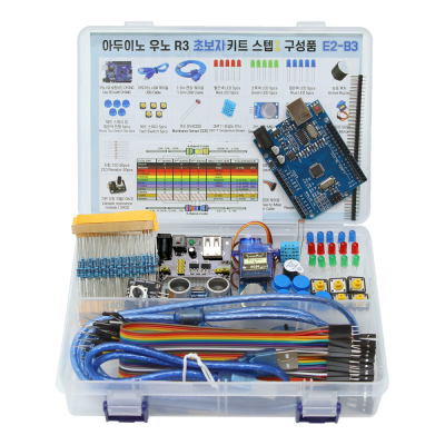
- 아두이노 우노 R3 초보자 키트 스텝 1
- 아두이노 실습을 위한 필수 부품이 포함된 키트, 특히 아두이노 코딩 배우기 교재를 따로 구매 하실 수 있는 제품입니다.
- 판매가 ₩ 24,200
-
8,920
-
- 조건부 무료배송
-
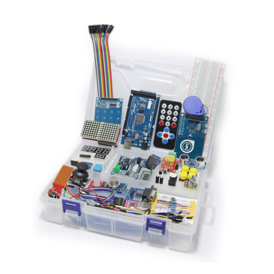
- 아두이노 메가 2560 고급 키트
- 아두이노 우노 R3보다 많은 입출력포트 확보가 가능하여 다양한 확장모듈 연동이 가능한 키트로 번거로운 케이블 연결을 최소화한 전문엔지니어를 위한 메가2560기반 아두이노 고급 키트
- 판매가 ₩ 132,000
-
9,999+
-
- 조건부 무료배송
-
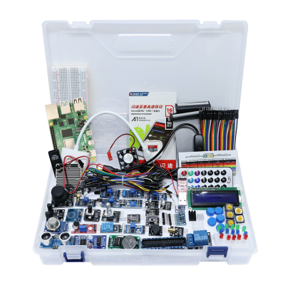
- 라즈베리파이 고급 키트
- 다양한 입출력-센서-디스플레이-통신-인터페이스 모듈 및 기타 액세서리로 구성된 울티메이트 라즈베리파이 키트
- 판매가 ₩ 99,000
-
1,832
-
- 조건부 무료배송
판매자 관련상품
-
![[로봇사이언스몰][코딩로봇] 알파 미니 (ALPHA MINI)](/data/goods/1/2020/06/15334_tmp_32a415fdf174c952317188293d01b0684901view.jpg)
- [로봇사이언스몰][코딩로봇] 알파 미니 (ALPHA MINI)
- 로봇을 활용한 재미있는 코딩학습
- 판매가 ₩ 1,250,000
-
9,999+
-
- 조건부 무료배송
-
- [로봇사이언스몰] 메이커스: 어른의 과학 Vol.06 이공계 연구소 보드게임
- 이과생 마음 두근거리게 하는, 과학자가 만든 과학자 되어보기 보드게임
- 판매가 ₩ 78,000
-
1,421
-
- 조건부 무료배송
-
![[로봇사이언스몰][블루이노] 스마트팜 인공지능 키트](/data/goods/1/2021/05/17457_temp_16218314494856view.png)
- [로봇사이언스몰][블루이노] 스마트팜 인공지능 키트
- 인공지능이 가미 된 내가 직접 스마트팜을 구축하고 식물을 키워볼 수 있는 키트입니다.
- 판매가 ₩ 638,000
-
9,999+
-
- 조건부 무료배송
-
![[로봇사이언스몰][교육용드론][CoDrone] 코드론 미니](/data/goods/1/2020/01/14879_tmp_f6cf2ca48125c96d1f029e73a51f1bd87855view.png)
- [로봇사이언스몰][교육용드론][CoDrone] 코드론 미니
- 코딩이 가능한 미니드론/안정적 군집 비행 3대
- 판매가 ₩ 99,000
-
9,999+
-
- 조건부 무료배송
판매자 정보
| 판매자 | 본사 | 셀러등급 | |
|---|---|---|---|
| 상호명 | (주)위키모바일(로봇사이언스몰) | 대표자 | 김경식 |
| 사업자등록번호 | 215-87-14086 | 통신판매신고번호 | 제2008-서울송파-0867호 |
| 연락처 | 02-2283-1300 | 사업장 소재지 | 서울특별시 송파구 문정동 643-1 엠스테이트 B동704호 |
2. 해외구매 특성상 주문에서 배송까지는 평균 10~15일이 소요됩니다. 간혹 현지 제품 수급에 따라 부득이하게 시일이 더 소요 될 수 있으니 구매시 좀 더 여유있게 주문하시길 권합니다.
3. 해외 내수품인 관계로 A/S에 대해서는 별도의 책임을 지지 않습니다.
4. 해외배송 특성상 주문접수후 배송상태가 배송준비중으로 넘어간 경우 해외에서 국내로의 배송이 이루어지고 있다는 뜻입니다. 따라서 배송준비중으로 배송상태가 넘어간 경우 취소및 반품이 불가하므로 이점 양해 부탁드립니다.
5. 타 해외구매대행 사이트에서 주문하신 물건과 주문날짜가 겹치지않도록 주의해 주십시오. 통관날짜가 같을 경우 합산관세가 부가되게 됩니다.