|
|
|
||||||||||||||||||||


|
|||||||||||||||||||


 물품구매안내")


 톡톡
톡톡- 모터, 서보모터, 스텝모터 드라이버 및 컨트롤러
-
[로봇사이언스몰][Pololu][폴로루] BD65496MUV Single Brushed DC Motor Driver Carrier #2960
상품번호 : 12118 아이콘 설명보기
![[로봇사이언스몰][로봇사이언스몰][Pololu][폴로루] BD65496MUV Single Brushed DC Motor Driver Carrier #2960>>모터, 서보모터, 스텝모터 드라이버 및 컨트롤러](/data/goods/1/2018/03/12118_tmp_1e0eecb5ecf475a85f5a20363e64ca0b4820view.jpg)
![[로봇사이언스몰][로봇사이언스몰][Pololu][폴로루] BD65496MUV Single Brushed DC Motor Driver Carrier #2960>>모터, 서보모터, 스텝모터 드라이버 및 컨트롤러](/data/goods/1/2018/03/12118_tmp_9184bb413a2ed4ed1269ed3bd30f95989969view.jpg)


[로봇사이언스몰][Pololu][폴로루] BD65496MUV Single Brushed DC Motor Driver Carrier #2960
This compact breakout board for ROHM’s BD65496MUV motor driver offers an operating voltage range of 2 V to 16 V and can deliver a continuous 1.2 A (5 A peak for a few milliseconds) to a single brushed DC motor. The motor driver features variable switching speed, allowing for PWM frequencies up to 500 kHz, two drive mode options, and built-in under-voltage and over-temperature protection; our carrier also adds reverse-voltage protection.
Overview

Features
Included hardware


Two 1×6-pin breakaway 0.1″ male headers are included with the BD65496MUV motor driver carrier, which can be soldered in to use the driver with breadboards, perfboards, or 0.1″ female connectors. (The headers might ship as a single 1×12 piece that can be broken in half.) The right picture above shows the two possible board orientations when used with these header pins (parts visible or silkscreen visible). You can also solder your motor leads and other connections directly to the board.
Using the motor driver

Motor and power connections are made on one side of the board and control connections are made on the other. The driver requires an operating voltage between 2 V and 16 V to be supplied to the reverse-protected power input, VIN, and a logic voltage between 2.5 V and 5.5 V to be supplied to the VCC pin; the logic voltage can typically be supplied by or shared with the controlling device.
The BD65496MUV offers two possible control interface modes: IN/IN and EN/IN. The PWM (MODE) pin is used to select the control interface. If the PWM (MODE) pin is left disconnected or driven low, as shown in the minimal wiring diagram above, the selected interface is IN/IN, which generally requires two PWM signals, one for INA and another for INB. If this pin is driven high, as shown in the wiring diagram below, the selected interface is EN/IN, which turns the INB pin into a “motor direction” input and the INA pin into an enable input that can be supplied with a PWM signal to control speed.

The PS (power save) pin can be driven low to put the driver into a low-power state and turn off the motor outputs, which is useful if you want to let the motor coast. The PS pin is pulled high through a 47 kΩ pull-up resistor on the carrier board so that the driver is enabled by default; the quiescent current draw of the board will be dominated by the current through this resistor when the pin is driven low to put the driver to sleep. In most applications, this pin can be left disconnected or can serve primarily as a way to enable coasting. For applications where a low-power mode is desirable, the 47 kΩ pull-up resistor can be removed (this resistor is located right next to the PS pin), or the logic voltage (VCC) for the driver can be dynamically supplied by a digital output of your microcontroller.
The following truth table (taken directly from the BD65496MUV datasheet) shows how the driver operates:

Pinout

| PIN | Default State | Description |
|---|---|---|
| VIN | Reverse-protected power supply input; supply this pin with 2 V to 16 V. | |
| VCC | 2.5 V to 5.5 V logic power supply connection. Logic supply current draw is typically only a few milliamps at most, so in many applications this pin can optionally be dynamically powered by a microcontroller digital output. | |
| GND | Ground connection points for the motor and logic supplies. The control source and the motor driver must share a common ground. | |
| OUTA | H-bridge output A. | |
| OUTB | H-bridge output B. | |
| PWM (MODE) | LOW | Drive mode selection pin. LOW=IN/IN; HIGH=EN/IN. |
| INA | LOW | Motor control input A (functions like an enable pin in EN/IN mode). |
| INB | LOW | Motor control input B (functions like a direction pin in EN/IN mode). |
| PS | HIGH | Sleep/coast input. Drive low to tri-state the driver outputs and enable power-save mode. |
| TR1 | LOW | Turn-on and turn-off time selection input 1. |
| TR2 | LOW | Turn-on and turn-off time selection input 2. |
All of the driver inputs except PS are internally pulled low through 100 kΩ pull-down resistors. The PS pin is pulled high on the carrier board through a 47 kΩ pull-up resistor that overpowers the driver IC’s internal 300 kΩ pull-down.
The TR1 and TR2 pins control the driver’s turn-on and turn-off time. Both pins are low by default, resulting in a default turn-on time of 150 ns (typical) and a default turn-off time of 50 ns (typical); this allows for PWM frequencies up to 500 kHz. If such a high switching frequency is not required, the TR1 and TR2 inputs can be configured for longer turn-on and turn-off times to help reduce electromagnetic interference (EMI). See the datasheet for more information.
Real-world power dissipation considerations
The BD65496MUV datasheet rates this driver for a maximum continuous current of 1.2 A. In our tests, we found that the chip was able to deliver 1.2 A comfortably over the full operating voltage range, with the driver temperature only approaching the thermal shut down point at the very low end of the motor supply range. At 9 V in, we did not see the driver’s thermal shutdown activate until we pushed the continuous current past 1.5 A for many minutes, but we generally advise against running so close to the limit that the driver overheats. Our tests were conducted at 100% duty cycle with no forced air flow; PWMing the motor will introduce additional heating proportional to the frequency.
This product can get hot enough to burn you long before the chip overheats. Take care when handling this product and other components connected to it.
Schematic

Dimensions
| Size: | 0.6″ × 0.6″1 |
|---|---|
| Weight: | 0.6 g1 |
General specifications
| Motor driver: | BD65496MUV |
|---|---|
| Motor channels: | 1 |
| Minimum operating voltage: | 2 V |
| Maximum operating voltage: | 16 V |
| Continuous output current per channel: | 1.2 A |
| Peak output current per channel: | 5 A2 |
| Maximum PWM frequency: | 500 kHz3 |
| Minimum logic voltage: | 2.5 V |
| Maximum logic voltage: | 5.5 V |
| Reverse voltage protection?: | Y |
Notes:
- 1
- Without included hardware.
- 2
- For no longer than 10 ms; duty cycle < 5%.
- 3
- TR1 and TR2 low.
File downloads
- ROHM BD65496MUV DC motor driver datasheet (481k pdf)
- BD65496MUV single brushed DC motor driver carrier schematic diagram (139k pdf)
- Printable schematic for the BD65496MUV single brushed DC motor driver carrier.
- Drill guide for the BD65496MUV Single Brushed DC Motor Driver Carrier (28k dxf)
- This DXF drawing shows the locations of all of the board’s holes.
- Dimension diagram of the BD65496MUV Single Brushed DC Motor Driver Carrier (287k pdf)
- 3D model of the BD65496MUV Single Brushed DC Motor Driver Carrier (3MB step)
Recommended links
- ROHM BD65496MUV product page
- ROHM’s product page for the BD65496MUV, where you can find the latest datasheet and additional resources.
 아이콘이 부착된 상품
 b. 해외상품 :
1) 해당상품:  아이콘이 부착된 상품
2) 구매금액 700,000원 이상 : 입금확인 후 최소 5일 ~ 최대 2주
3) 구매금액 700,000원 이하 : 입금확인 후 최소 1주 ~ 최대 8주
4) 단, 해외계약업체에 품절되지 않은 상품에 한함
② 구매상품 종류가 많을 경우 예상 준비기간 보다 더 소요 될 수 있습니다.
③ 주문하신 상품은 출고완료 메일 또는 문자 수신 후 익일~최대7일(도서,산간지역)
이내에 수령하실 수 있습니다.
④ 제주(\3,500원)/도서지역(\5,000원)은 배송비가 추가됩니다.
제주,도서, 산간지역은 타 지역보다 배송기간이 길어질 수 있습니다.
⑤  아이콘이 부착된 상품이라도 국내재고가 있을 수 있습니다.
⑥ 해외 현지 사정으로 인해 공지한 배송기간보다 더 길어 질 수 있습니다.
⑦ 해외상품은 반품/교환/취소가 어려울 수 있으니 신중히 주문하시기 바랍니다.
3. 소비자의 단순변심/착오구매에 의한 청약철회제한안내
① 전자상거래 등에서의 소비자보호에 관한 법률 제17조 제2항 및 동 시행령
제21조에 의한 청약철회 제한 사유에 해당하는 경우 및 기타 객관적으로
이에 준하는 것으로 인정되는 경우에 한합니다.
② 소비자의 단순변심, 착오구매에 의한 교환/반품 시에 발생하는 배송비는
소비자가 부담합니다.
③ 판매자의 실수,제품하자 등의 사유로 인한 배송비는 판매자가 부담합니다.
4. 상품의 교환/반품/보증조건 및 품질보증기준안내
① 상품이 공급된 날(배송완료일)로부터 7일 이내에 교환/반품을 신청 할 수 있습니다.
그러나 아래의 사유에 해당 하는 경우에는 교환/반품 신청이 받아들여지지 않을 수도 있습니다.
a. 소비자의 책임으로 인해 상품이 훼손/멸실 된 경우(확인을 위한 포장훼손제외)
b. 소비자의 사용에 의해 상품의 가치가 현저하게 감소한 경우
c. 시간의 경과로 인해 상품의 재판매가 불가하게 된 경우
d. 판매방식의 특성으로 판매자에게 회복할 수 없는 피해가 발생한 경우 (주문제작 상품, 청약철회상품 등)
② 교환/반품/보증조건 및 품질보증기준은 『소비자기본법』에 따른 소비자분쟁해결기준에 따라 피해를 보상합니다.
5. 소비자피해보상 처리, 재화 등에 대한 불만 및 분쟁처리 안내
관련상품
-
![[로봇사이언스몰] 메이커스: 어른의 과학 Vol.06 이공계 연구소 보드게임](/data/goods/1/2022/10/20106_temp_16655616023677view.png)


- [로봇사이언스몰] 메이커스: 어른의 과학 Vol.06 이공계 연구소 보드게임
- 이과생 마음 두근거리게 하는, 과학자가 만든 과학자 되어보기 보드게임
- 판매가 ₩ 78,000
-
 1,440
1,440
-
- 조건부 무료배송
-
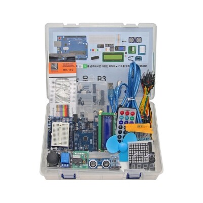
- 아두이노 우노 R3 고급 키트
- 아두이노 실습을 위한 필수 부품이 포함된 키트, 아두이노 코딩 배우기 교재가 제외된 상품입니다.
- 판매가 ₩ 65,340
-
6,683
-
- 조건부 무료배송
-
![[로봇사이언스몰][코딩로봇] 알파 미니 (ALPHA MINI)](/data/goods/1/2020/06/15334_tmp_32a415fdf174c952317188293d01b0684901view.jpg)
- [로봇사이언스몰][코딩로봇] 알파 미니 (ALPHA MINI)
- 로봇을 활용한 재미있는 코딩학습
- 판매가 ₩ 1,250,000
-
9,999+
-
- 조건부 무료배송
-
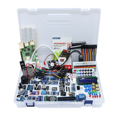
- 라즈베리파이 고급 키트
- 다양한 입출력-센서-디스플레이-통신-인터페이스 모듈 및 기타 액세서리로 구성된 울티메이트 라즈베리파이 키트
- 판매가 ₩ 99,000
-
1,884
-
- 조건부 무료배송
판매자 관련상품
-
- [로봇사이언스몰][코딩로봇] 알파 미니 (ALPHA MINI)
- 로봇을 활용한 재미있는 코딩학습
- 판매가 ₩ 1,250,000
-
9,999+
-
- 조건부 무료배송
-
- [로봇사이언스몰] 메이커스: 어른의 과학 Vol.06 이공계 연구소 보드게임
- 이과생 마음 두근거리게 하는, 과학자가 만든 과학자 되어보기 보드게임
- 판매가 ₩ 78,000
-
1,440
-
- 조건부 무료배송
-
![[로봇사이언스몰][블루이노] 스마트팜 인공지능 키트](/data/goods/1/2021/05/17457_temp_16218314494856view.png)
- [로봇사이언스몰][블루이노] 스마트팜 인공지능 키트
- 인공지능이 가미 된 내가 직접 스마트팜을 구축하고 식물을 키워볼 수 있는 키트입니다.
- 판매가 ₩ 638,000
-
9,999+
-
- 조건부 무료배송
-
![[로봇사이언스몰][교육용드론][CoDrone] 코드론 미니](/data/goods/1/2020/01/14879_tmp_f6cf2ca48125c96d1f029e73a51f1bd87855view.png)
- [로봇사이언스몰][교육용드론][CoDrone] 코드론 미니
- 코딩이 가능한 미니드론/안정적 군집 비행 3대
- 판매가 ₩ 99,000
-
9,999+
-
- 조건부 무료배송
판매자 정보
| 판매자 | 본사 | 셀러등급 | |
|---|---|---|---|
| 상호명 | (주)위키모바일(로봇사이언스몰) | 대표자 | 김경식 |
| 사업자등록번호 | 215-87-14086 | 통신판매신고번호 | 제2008-서울송파-0867호 |
| 연락처 | 02-2283-1300 | 사업장 소재지 | 서울특별시 송파구 문정동 643-1 엠스테이트 B동704호 |
2. 해외구매 특성상 주문에서 배송까지는 평균 10~15일이 소요됩니다. 간혹 현지 제품 수급에 따라 부득이하게 시일이 더 소요 될 수 있으니 구매시 좀 더 여유있게 주문하시길 권합니다.
3. 해외 내수품인 관계로 A/S에 대해서는 별도의 책임을 지지 않습니다.
4. 해외배송 특성상 주문접수후 배송상태가 배송준비중으로 넘어간 경우 해외에서 국내로의 배송이 이루어지고 있다는 뜻입니다. 따라서 배송준비중으로 배송상태가 넘어간 경우 취소및 반품이 불가하므로 이점 양해 부탁드립니다.
5. 타 해외구매대행 사이트에서 주문하신 물건과 주문날짜가 겹치지않도록 주의해 주십시오. 통관날짜가 같을 경우 합산관세가 부가되게 됩니다.