|
|
|
||||||||||||||||||||


|
|||||||||||||||||||


 물품구매안내")


 톡톡
톡톡- 모터, 서보모터, 스텝모터 드라이버 및 컨트롤러
-
[로봇사이언스몰][Pololu][폴로루] A4988 Stepper Motor Driver Carrier, Black Edition #2128
상품번호 : 12210 아이콘 설명보기
![[로봇사이언스몰][로봇사이언스몰][Pololu][폴로루] A4988 Stepper Motor Driver Carrier, Black Edition #2128>>모터, 서보모터, 스텝모터 드라이버 및 컨트롤러](/data/goods/1/2018/03/12210_tmp_d9ebad56fc8725d22f939c4cba32f64d0305view.jpg)
![[로봇사이언스몰][로봇사이언스몰][Pololu][폴로루] A4988 Stepper Motor Driver Carrier, Black Edition #2128>>모터, 서보모터, 스텝모터 드라이버 및 컨트롤러](/data/goods/1/2018/03/12210_tmp_ed14391672a8052e4cd387057d1dcb382471view.jpg)


[로봇사이언스몰][Pololu][폴로루] A4988 Stepper Motor Driver Carrier, Black Edition #2128
Our Black Edition A4988 stepper motor driver carrier is a higher-performance drop-in replacement for the original A4988 stepper motor driver carrier. It features a four-layer PCB for better thermal performance, allowing the A4988 microstepping bipolar stepper motor driver to deliver approximately 20% more current than our two-layer (green) version. Like our original carrier, the Black Edition offers adjustable current limiting, over-current and over-temperature protection, and five different microstep resolutions. It operates from 8 V to 35 V and can deliver up to 2 A per coil with sufficient additional cooling. This board ships with 0.1″ male header pins included but not soldered in.
Overview

This product is a carrier board or breakout board for Allegro’s A4988 DMOS Microstepping Driver with Translator and Overcurrent Protection; we therefore recommend careful reading of the A4988 datasheet (1MB pdf) before using this product. This stepper motor driver lets you control one bipolar stepper motor at up to 2 A output current per coil (see the Power Dissipation Considerations section below for more information). Here are some of the driver’s key features:
This product ships with all surface-mount components—including the A4988 driver IC—installed as shown in the product picture.
This product ships individually packaged with 0.1″ male header pins included but not soldered in; we also carry a version with male header pins already soldered in. For customers interested in higher volumes at lower unit costs, we offer a bulk-packaged version without header pins and a bulk-packaged version with header pins installed.
The Black Edition has the same component layout and pinout as our A4988 stepper motor driver carrier, so it can be used as a higher-performance drop-in replacement in applications designed for our original drivers. The Black Edition achieves its higher performance through its four-layer printed circuit board (PCB), which better draws heat out of the A4988 driver—while our original carrier can deliver up to approximately 1 A per phase in full-step mode without a heat sink or air flow, the Black Edition can deliver up to approximately 1.2 A under the same conditions.
Note that we carry several other stepper motor drivers that can be used as alternatives for this module (and drop-in replacements in many applications):
We also sell a larger version of the A4988 carrier that has reverse power protection on the main power input and built-in 5 V and 3.3 V voltage regulators that eliminate the need for separate logic and motor supplies.
Some unipolar stepper motors (e.g. those with six or eight leads) can be controlled by this driver as bipolar stepper motors. For more information, please see the frequently asked questions. Unipolar motors with five leads cannot be used with this driver.
Included hardware
The A4988 stepper motor driver carrier comes with one 1×16-pin breakaway 0.1" male header. The headers can be soldered in for use with solderless breadboards or 0.1" female connectors. You can also solder your motor leads and other connections directly to the board. (A version of this board with headers already installed is also available.)


Using the driver

Power connections
The driver requires a logic supply voltage (3 – 5.5 V) to be connected across the VDD and GND pins and a motor supply voltage (8 – 35 V) to be connected across VMOT and GND. These supplies should have appropriate decoupling capacitors close to the board, and they should be capable of delivering the expected currents (peaks up to 4 A for the motor supply).
Warning: This carrier board uses low-ESR ceramic capacitors, which makes it susceptible to destructive LC voltage spikes, especially when using power leads longer than a few inches. Under the right conditions, these spikes can exceed the 35 V maximum voltage rating for the A4988 and permanently damage the board, even when the motor supply voltage is as low as 12 V. One way to protect the driver from such spikes is to put a large (at least 47 µF) electrolytic capacitor across motor power (VMOT) and ground somewhere close to the board.
Motor connections
Four, six, and eight-wire stepper motors can be driven by the A4988 if they are properly connected; a FAQ answer explains the proper wirings in detail.
Warning: Connecting or disconnecting a stepper motor while the driver is powered can destroy the driver. (More generally, rewiring anything while it is powered is asking for trouble.)
Step (and microstep) size
Stepper motors typically have a step size specification (e.g. 1.8° or 200 steps per revolution), which applies to full steps. A microstepping driver such as the A4988 allows higher resolutions by allowing intermediate step locations, which are achieved by energizing the coils with intermediate current levels. For instance, driving a motor in quarter-step mode will give the 200-step-per-revolution motor 800 microsteps per revolution by using four different current levels.
The resolution (step size) selector inputs (MS1, MS2, and MS3) enable selection from the five step resolutions according to the table below. MS1 and MS3 have internal 100kΩ pull-down resistors and MS2 has an internal 50kΩ pull-down resistor, so leaving these three microstep selection pins disconnected results in full-step mode. For the microstep modes to function correctly, the current limit must be set low enough (see below) so that current limiting gets engaged. Otherwise, the intermediate current levels will not be correctly maintained, and the motor will skip microsteps.
| MS1 | MS2 | MS3 | Microstep Resolution |
|---|---|---|---|
| Low | Low | Low | Full step |
| High | Low | Low | Half step |
| Low | High | Low | Quarter step |
| High | High | Low | Eighth step |
| High | High | High | Sixteenth step |
Control inputs
Each pulse to the STEP input corresponds to one microstep of the stepper motor in the direction selected by the DIR pin. Note that the STEP and DIR pins are not pulled to any particular voltage internally, so you should not leave either of these pins floating in your application. If you just want rotation in a single direction, you can tie DIR directly to VCC or GND. The chip has three different inputs for controlling its many power states: RST, SLP, and EN. For details about these power states, see the datasheet. Please note that the RST pin is floating; if you are not using the pin, you can connect it to the adjacent SLP pin on the PCB to bring it high and enable the board.
Current limiting
One way to maximize stepper motor performance is to use as high of a voltage as is practical for your application. In particular, increasing the voltage generally allows for higher step rates and stepping torque since the current can change more quickly in the coils after each step. However, in order to safely use voltages above the rated voltage of a stepper motor, the coil current must be actively limited to keep it from exceeding the motor’s rated current.
The A4988 supports such active current limiting, and the trimmer potentiometer on the board can be used to set the current limit. One way to set the current limit is to put the driver into full-step mode and measure the current running through a single motor coil while adjusting the current limit potentiometer. This should be done with the motor holding a fixed position (i.e. without clocking the STEP input). Note that the current you are measuring is only 70% of the actual current limit setting, since both coils are always on and limited to this value in full-step mode, so if you later enable microstepping modes, the current through the coils will be able to exceed this measured full-step current by 40% (1/0.7) on certain steps; please take this into account when using this method to set the current limit. Also, note that you will need to perform this adjustment again if you ever change the logic voltage, Vdd, since the reference voltage that sets the current limit is a function of Vdd.
Note: The coil current can be very different from the power supply current, so you should not use the current measured at the power supply to set the current limit. The appropriate place to put your current meter is in series with one of your stepper motor coils.
Another way to set the current limit is to calculate the reference voltage that corresponds to your desired current limit and then adjust the current limit potentiometer until you measure that voltage on the VREF pin. The VREF pin voltage is accessible on a via that is circled on the bottom silkscreen of the circuit board. The current limit, IMAX, relates to the reference voltage as follows:
or, rearranged to solve for VREF:
RCS is the current sense resistance; original versions of this board used 0.050 Ω current sense resistors, but we switched to using 0.068 Ω current sense resistors in January 2017, which makes more of the adjustment potentiometer’s range useful. The following picture shows how to identify which current sense resistors your board has:

So, for example, if you want to set the current limit to 1 A and you have a board with 68 mΩ sense resistors, you would set VREF to 540 mV. Doing this ensures that even though the current through each coil changes from step to step, the magnitude of the current vector in the stepper motor stays constant at 1 A:
If you instead want the current through each coil to be 1 A in full-step mode, you would need to set the current limit to be 40% higher, or 1.4 A, since the coils are limited to approximately 70% of the set current limit in full-step mode (the equation above shows why this is the case). To do this with a board with 68 mΩ sense resistors, you would set VREF to 770 mV.
Power dissipation considerations
The A4988 driver IC has a maximum current rating of 2 A per coil, but the actual current you can deliver depends on how well you can keep the IC cool. The carrier’s printed circuit board is designed to draw heat out of the IC, but to supply more than approximately 1.2 A per coil, a heat sink or other cooling method is required (in our tests, we were able to deliver approximately 1.4 A per coil with air flow from a PC fan and no heat sink).
This product can get hot enough to burn you long before the chip overheats. Take care when handling this product and other components connected to it.
Please note that measuring the current draw at the power supply will generally not provide an accurate measure of the coil current. Since the input voltage to the driver can be significantly higher than the coil voltage, the measured current on the power supply can be quite a bit lower than the coil current (the driver and coil basically act like a switching step-down power supply). Also, if the supply voltage is very high compared to what the motor needs to achieve the set current, the duty cycle will be very low, which also leads to significant differences between average and RMS currents.
Schematic diagram

Dimensions
| Size: | 0.6″ × 0.8″ |
|---|---|
| Weight: | 1.5 g1 |
General specifications
| Minimum operating voltage: | 8 V |
|---|---|
| Maximum operating voltage: | 35 V |
| Continuous current per phase: | 1.2 A2 |
| Maximum current per phase: | 2 A3 |
| Minimum logic voltage: | 3 V |
| Maximum logic voltage: | 5.5 V |
| Microstep resolutions: | full, 1/2, 1/4, 1/8, and 1/16 |
| Reverse voltage protection?: | N |
| Bulk packaged: | N |
| Header pins soldered: | N4 |
Notes:
- 1
- Without included optional headers.
- 2
- Without a heat sink or forced air flow.
- 3
- With sufficient additional cooling.
- 4
- Male header pins are included for the board's 16 holes, but they are not installed.
File downloads
- Allegro A4988 stepper motor driver datasheet (1MB pdf)
- Dimension diagram of the A4988 Stepper Motor Driver Carrier, Black Edition (231k pdf)
- 3D model of the A4988 Stepper Motor Driver Carrier, Black Edition (3MB step)
- A4988 Stepper Motor Driver Carrier drill guide (33k dxf)
- This DXF drawing shows the locations of all of the board’s holes. It applies to both the green (md09b) and black (md09c) editions of the A4988 stepper motor driver carrier.
Recommended links
- Video: setting the current limit on Pololu stepper motor driver carriers
- Pololu A4988 stepper motor driver carrier assembly video
- A short video showing the in-house assembly of a panel of Black Edition A4988 stepper motor driver carriers on our Samsung SM421F pick and place machine.
- Pololu A4983/A4988 Stepper Motor Driver Carrier Kicad module
- A customer-made module for using the Pololu A4983/A4988 Stepper Motor Driver Carrier in Kicad. By Jared Harvey, October 2011.
- Arduino library for A4988, DRV8825, DRV8834, DRV8880
- This Arduino library, written by forum member laurb9, allows users to control a stepper motor with our A4988, DRV8825, or DRV8834 carriers. The library has functions that enable users to set rotational rate, change microstepping mode, and specify how many steps to take or specify how many degrees to rotate.
 아이콘이 부착된 상품
 b. 해외상품 :
1) 해당상품:  아이콘이 부착된 상품
2) 구매금액 700,000원 이상 : 입금확인 후 최소 5일 ~ 최대 2주
3) 구매금액 700,000원 이하 : 입금확인 후 최소 1주 ~ 최대 8주
4) 단, 해외계약업체에 품절되지 않은 상품에 한함
② 구매상품 종류가 많을 경우 예상 준비기간 보다 더 소요 될 수 있습니다.
③ 주문하신 상품은 출고완료 메일 또는 문자 수신 후 익일~최대7일(도서,산간지역)
이내에 수령하실 수 있습니다.
④ 제주(\3,500원)/도서지역(\5,000원)은 배송비가 추가됩니다.
제주,도서, 산간지역은 타 지역보다 배송기간이 길어질 수 있습니다.
⑤  아이콘이 부착된 상품이라도 국내재고가 있을 수 있습니다.
⑥ 해외 현지 사정으로 인해 공지한 배송기간보다 더 길어 질 수 있습니다.
⑦ 해외상품은 반품/교환/취소가 어려울 수 있으니 신중히 주문하시기 바랍니다.
3. 소비자의 단순변심/착오구매에 의한 청약철회제한안내
① 전자상거래 등에서의 소비자보호에 관한 법률 제17조 제2항 및 동 시행령
제21조에 의한 청약철회 제한 사유에 해당하는 경우 및 기타 객관적으로
이에 준하는 것으로 인정되는 경우에 한합니다.
② 소비자의 단순변심, 착오구매에 의한 교환/반품 시에 발생하는 배송비는
소비자가 부담합니다.
③ 판매자의 실수,제품하자 등의 사유로 인한 배송비는 판매자가 부담합니다.
4. 상품의 교환/반품/보증조건 및 품질보증기준안내
① 상품이 공급된 날(배송완료일)로부터 7일 이내에 교환/반품을 신청 할 수 있습니다.
그러나 아래의 사유에 해당 하는 경우에는 교환/반품 신청이 받아들여지지 않을 수도 있습니다.
a. 소비자의 책임으로 인해 상품이 훼손/멸실 된 경우(확인을 위한 포장훼손제외)
b. 소비자의 사용에 의해 상품의 가치가 현저하게 감소한 경우
c. 시간의 경과로 인해 상품의 재판매가 불가하게 된 경우
d. 판매방식의 특성으로 판매자에게 회복할 수 없는 피해가 발생한 경우 (주문제작 상품, 청약철회상품 등)
② 교환/반품/보증조건 및 품질보증기준은 『소비자기본법』에 따른 소비자분쟁해결기준에 따라 피해를 보상합니다.
5. 소비자피해보상 처리, 재화 등에 대한 불만 및 분쟁처리 안내
관련상품
-
![[로봇사이언스몰] 메이커스: 어른의 과학 Vol.06 이공계 연구소 보드게임](/data/goods/1/2022/10/20106_temp_16655616023677view.png)


- [로봇사이언스몰] 메이커스: 어른의 과학 Vol.06 이공계 연구소 보드게임
- 이과생 마음 두근거리게 하는, 과학자가 만든 과학자 되어보기 보드게임
- 판매가 ₩ 78,000
-
 1,334
1,334
-
- 조건부 무료배송
-
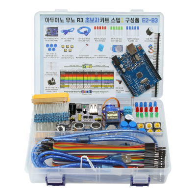
- 아두이노 우노 R3 초보자 키트 스텝 1
- 아두이노 실습을 위한 필수 부품이 포함된 키트, 특히 아두이노 코딩 배우기 교재를 따로 구매 하실 수 있는 제품입니다.
- 판매가 ₩ 24,200
-
8,837
-
- 조건부 무료배송
-
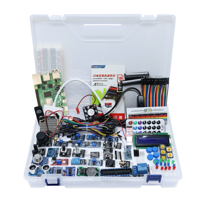
- 라즈베리파이 고급 키트
- 다양한 입출력-센서-디스플레이-통신-인터페이스 모듈 및 기타 액세서리로 구성된 울티메이트 라즈베리파이 키트
- 판매가 ₩ 99,000
-
1,777
-
- 조건부 무료배송
-
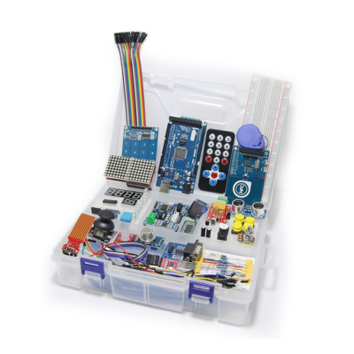
- 아두이노 메가 2560 고급 키트
- 아두이노 우노 R3보다 많은 입출력포트 확보가 가능하여 다양한 확장모듈 연동이 가능한 키트로 번거로운 케이블 연결을 최소화한 전문엔지니어를 위한 메가2560기반 아두이노 고급 키트
- 판매가 ₩ 132,000
-
9,999+
-
- 조건부 무료배송
판매자 관련상품
-
- [로봇사이언스몰] 메이커스: 어른의 과학 Vol.06 이공계 연구소 보드게임
- 이과생 마음 두근거리게 하는, 과학자가 만든 과학자 되어보기 보드게임
- 판매가 ₩ 78,000
-
1,334
-
- 조건부 무료배송
-
![[로봇사이언스몰][코딩로봇] 알파 미니 (ALPHA MINI)](/data/goods/1/2020/06/15334_tmp_32a415fdf174c952317188293d01b0684901view.jpg)
- [로봇사이언스몰][코딩로봇] 알파 미니 (ALPHA MINI)
- 로봇을 활용한 재미있는 코딩학습
- 판매가 ₩ 1,250,000
-
9,999+
-
- 조건부 무료배송
-
![[로봇사이언스몰][블루이노] 스마트팜 인공지능 키트](/data/goods/1/2021/05/17457_temp_16218314494856view.png)
- [로봇사이언스몰][블루이노] 스마트팜 인공지능 키트
- 인공지능이 가미 된 내가 직접 스마트팜을 구축하고 식물을 키워볼 수 있는 키트입니다.
- 판매가 ₩ 638,000
-
9,999+
-
- 조건부 무료배송
-
![[로봇사이언스몰][인공지능] 주미 (Zumi)](/data/goods/1/2020/01/14877_tmp_f4aae8406fbd98ceb600ef6585cd0c510799view.png)
- [로봇사이언스몰][인공지능] 주미 (Zumi)
- 인공지능 자동차
- 판매가 ₩ 242,000
-
9,999+
-
- 조건부 무료배송
판매자 정보
| 판매자 | 본사 | 셀러등급 | |
|---|---|---|---|
| 상호명 | (주)위키모바일(로봇사이언스몰) | 대표자 | 김경식 |
| 사업자등록번호 | 215-87-14086 | 통신판매신고번호 | 제2008-서울송파-0867호 |
| 연락처 | 02-2283-1300 | 사업장 소재지 | 서울특별시 송파구 문정동 643-1 엠스테이트 B동704호 |
2. 해외구매 특성상 주문에서 배송까지는 평균 10~15일이 소요됩니다. 간혹 현지 제품 수급에 따라 부득이하게 시일이 더 소요 될 수 있으니 구매시 좀 더 여유있게 주문하시길 권합니다.
3. 해외 내수품인 관계로 A/S에 대해서는 별도의 책임을 지지 않습니다.
4. 해외배송 특성상 주문접수후 배송상태가 배송준비중으로 넘어간 경우 해외에서 국내로의 배송이 이루어지고 있다는 뜻입니다. 따라서 배송준비중으로 배송상태가 넘어간 경우 취소및 반품이 불가하므로 이점 양해 부탁드립니다.
5. 타 해외구매대행 사이트에서 주문하신 물건과 주문날짜가 겹치지않도록 주의해 주십시오. 통관날짜가 같을 경우 합산관세가 부가되게 됩니다.